Table of contents:
What is Ohm’s Law? It’s a fundamental principle that governs the relationship between voltage, current, and resistance in electrical circuits. Imagine a river flowing downhill; the water represents the current, the slope of the hill represents the voltage, and the rocks in the riverbed represent the resistance. This simple analogy helps us understand how Ohm’s Law governs the flow of electricity.
Discovered by Georg Simon Ohm in the 19th century, this law revolutionized our understanding of electricity. It provided a mathematical framework for analyzing and designing electrical circuits, laying the foundation for modern electronics.
Introduction to Ohm’s Law
Ohm’s Law is a fundamental principle in electrical engineering that describes the relationship between voltage, current, and resistance in a circuit. It states that the current flowing through a conductor is directly proportional to the voltage applied across its ends and inversely proportional to the resistance of the conductor. This simple yet powerful law provides a foundation for understanding and analyzing various electrical circuits and devices.
Historical Overview
Georg Simon Ohm, a German physicist, discovered the relationship between voltage, current, and resistance in 1827. He conducted experiments using a simple circuit consisting of a battery, a wire, and a thermometer. By varying the length and thickness of the wire, he observed how the current changed with the applied voltage. His meticulous measurements and analysis led to the formulation of Ohm’s Law, which revolutionized the understanding of electricity.
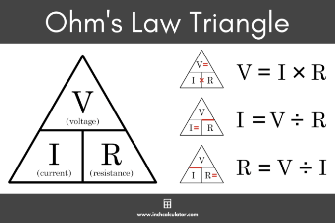
Ohm’s Law states that the current (I) flowing through a conductor is directly proportional to the voltage (V) applied across its ends and inversely proportional to the resistance (R) of the conductor.
Ohm’s groundbreaking work was initially met with skepticism from the scientific community. However, its importance was gradually recognized, and his findings were eventually accepted as a fundamental law of electricity. Ohm’s Law has been instrumental in the development of electrical engineering, enabling the design and analysis of electrical circuits and devices.
The Formula and its Components

Ohm’s Law is a fundamental principle in electrical engineering that describes the relationship between voltage, current, and resistance in a circuit. It is expressed in a simple mathematical formula, V = IR, which provides a framework for understanding and analyzing electrical circuits.
Understanding the Components of Ohm’s Law
The formula V = IR consists of three key components:
V = Voltage
I = Current
R = Resistance
Each component represents a distinct aspect of electrical behavior, and their interplay governs the flow of electricity in a circuit.
Voltage
Voltage is the electrical potential difference between two points in a circuit. It is the driving force that pushes electrons through a conductor, creating an electric current. Voltage is measured in Volts (V).
Current
Current is the flow of electrical charge through a conductor. It is measured in Amperes (A). One Ampere is equivalent to one Coulomb of charge passing a given point in a circuit per second.
Resistance
Resistance is the opposition to the flow of electrical current. It is a property of a material that determines how easily current can flow through it. Resistance is measured in Ohms (Ω).
Applications of Ohm’s Law

Ohm’s Law, a fundamental principle in electrical engineering, finds widespread applications in various real-world scenarios. It forms the bedrock for understanding and analyzing electrical circuits, predicting current flow, and designing electrical devices. This law is essential for troubleshooting electrical problems, ensuring efficient power delivery, and optimizing the performance of electrical systems.
Applications in Electrical Devices
Ohm’s Law plays a crucial role in the design and operation of various electrical devices. For example, in a light bulb, the resistance of the filament determines the amount of current that flows through it, which in turn dictates the brightness of the bulb. Similarly, in a heater, the resistance of the heating element determines the amount of heat generated. Ohm’s Law helps engineers to determine the appropriate resistance for each component to achieve the desired performance.
Applications in Electrical Circuits
Ohm’s Law is fundamental to analyzing and understanding electrical circuits. It helps in determining the voltage drop across a resistor, the current flowing through a circuit, or the resistance of a component. For instance, in a simple circuit consisting of a battery, a resistor, and a switch, Ohm’s Law can be used to calculate the current flowing through the resistor when the switch is closed.
Applications in Circuit Analysis, Troubleshooting, and Design
Ohm’s Law is essential for circuit analysis, troubleshooting, and design. By applying Ohm’s Law, engineers can determine the behavior of circuits, identify faulty components, and design circuits that meet specific performance requirements. For example, in a complex circuit with multiple components, Ohm’s Law can be used to analyze the voltage drop across each component and identify any potential problems. Additionally, Ohm’s Law can be used to calculate the power dissipated by each component, which is crucial for ensuring that components are not overloaded.
Understanding Resistance
Resistance is a fundamental concept in electrical circuits, playing a crucial role in controlling the flow of electric current. It’s like a bottleneck in a pipe, restricting the amount of water flowing through. The higher the resistance, the more it impedes the current.
Types of Resistors
Resistors are components specifically designed to introduce resistance into a circuit. They come in various types, each with unique characteristics and applications.
- Fixed Resistors: These resistors have a constant resistance value, typically indicated by color bands on their body. They are commonly used in circuits to limit current, divide voltage, or create specific voltage drops.
- Variable Resistors (Potentiometers): These resistors allow you to adjust their resistance value manually. They are often used as volume controls in audio systems, dimmer switches in lighting circuits, or to fine-tune the behavior of circuits.
- Thermistors: These resistors exhibit a change in resistance depending on their temperature. They are widely used in temperature sensors, control circuits, and other applications where temperature monitoring or control is crucial.
Factors Influencing Resistance
Several factors influence the resistance of a material or component:
- Material: Different materials have different inherent resistance properties. For instance, copper is a good conductor with low resistance, while rubber is an insulator with high resistance.
- Length: The longer the material, the greater the resistance. Imagine a longer pipe, which naturally restricts water flow more than a shorter one.
- Cross-Sectional Area: A larger cross-sectional area allows more current to flow, reducing resistance. Think of a wider pipe, allowing more water to pass through.
- Temperature: For most materials, resistance increases with temperature. This is because increased temperature causes atoms to vibrate more, hindering the flow of electrons.
Resistance is a measure of how much a material opposes the flow of electric current. It is measured in ohms (Ω).
Voltage and Current Relationship: What Is Ohm’s Law
Ohm’s Law establishes a fundamental relationship between voltage, current, and resistance in an electrical circuit. This relationship is crucial for understanding how electricity flows and how components behave within a circuit.
Voltage, often referred to as electrical potential difference, is the driving force that pushes electric charge through a circuit. Current, on the other hand, is the flow of electric charge through a conductor. Ohm’s Law states that the current flowing through a conductor is directly proportional to the voltage applied across its ends and inversely proportional to the resistance of the conductor.
Voltage Drives Current
Voltage, as the driving force, dictates the flow of current. Imagine a water pipe analogy: voltage is analogous to the water pressure, and current is analogous to the flow rate of water. Higher water pressure pushes more water through the pipe, just as a higher voltage pushes more current through a circuit. This relationship can be visualized using a simple circuit with a battery (voltage source) and a resistor.
The higher the voltage applied across the resistor, the greater the current flowing through it.
Consider a circuit with a 12-volt battery connected to a 10-ohm resistor. Using Ohm’s Law, we can calculate the current:
Current (I) = Voltage (V) / Resistance (R) = 12V / 10 ohms = 1.2 Amps
If we increase the voltage to 24 volts, the current will also double to 2.4 Amps. This demonstrates the direct proportionality between voltage and current.
Voltage Drop Across a Resistor
As current flows through a resistor, it encounters resistance, which impedes its flow. This impedance results in a voltage drop across the resistor, meaning that the voltage at the resistor’s end is lower than the voltage at its beginning. The voltage drop across a resistor is directly proportional to the current flowing through it and the resistance value.
Voltage Drop (V) = Current (I) x Resistance (R)
For instance, if 1 Amp of current flows through a 5-ohm resistor, the voltage drop across the resistor would be 5 volts. This means that if the voltage at the beginning of the resistor is 10 volts, the voltage at the end of the resistor would be 5 volts (10 volts – 5 volts).
Power and Ohm’s Law

Power, a fundamental concept in electrical circuits, represents the rate at which energy is transferred or consumed. It’s closely tied to voltage and current, the driving force and the flow of charge, respectively, in an electrical circuit. Ohm’s Law, which establishes the relationship between voltage, current, and resistance, provides a framework for understanding the interplay of these quantities and how they influence power.
Power, Voltage, and Current Relationship
Power is directly proportional to both voltage and current. This means that increasing either voltage or current will result in a proportional increase in power. The relationship can be expressed as:
P = VI
where:
* P represents power, measured in watts (W).
* V represents voltage, measured in volts (V).
* I represents current, measured in amperes (A).
This equation states that the power dissipated in a circuit is equal to the product of the voltage across the circuit and the current flowing through it.
Power Formula Derivation
The power formula can be derived using Ohm’s Law (V = IR). Substituting V = IR into the power equation (P = VI), we get:
P = (IR)I = I²R
Similarly, substituting I = V/R into the power equation (P = VI), we get:
P = V(V/R) = V²/R
Therefore, the power formula can be expressed in three equivalent forms:
* P = VI (power is the product of voltage and current)
* P = I²R (power is the square of current multiplied by resistance)
* P = V²/R (power is the square of voltage divided by resistance)
Power Dissipation in Resistors
Resistors are passive components that oppose the flow of current. When current flows through a resistor, energy is dissipated in the form of heat. This power dissipation is quantified by the power formula:
P = I²R
The higher the resistance or the current flowing through the resistor, the greater the power dissipated as heat. This phenomenon is known as Joule heating, and it’s a fundamental principle in many electrical applications.
For instance, in a light bulb, the filament acts as a resistor. When current flows through the filament, it heats up due to Joule heating, causing the filament to glow and emit light. The higher the power dissipated in the filament, the brighter the light bulb will shine.
Circuit Examples and Analysis
Let’s see how Ohm’s Law works in practice by examining simple circuit examples. Understanding how to analyze circuits using Ohm’s Law is crucial for comprehending electrical systems and designing circuits effectively.
Analyzing a Simple Circuit, What is ohm’s law
To illustrate the application of Ohm’s Law, consider a basic circuit consisting of a voltage source (battery), a resistor (light bulb), and a current path (wires).
This circuit can be analyzed using Ohm’s Law to calculate the voltage across the resistor, the current flowing through the circuit, or the resistance of the light bulb.
Applying Ohm’s Law in Circuit Analysis
Here’s a step-by-step guide on how to apply Ohm’s Law in circuit analysis:
1. Identify the known values: Determine the values that are given in the circuit problem. For example, you might be given the voltage of the battery and the resistance of the light bulb.
2. Identify the unknown value: Determine the value you need to calculate. For example, you might need to find the current flowing through the circuit.
3. Choose the appropriate formula: Select the Ohm’s Law formula that relates the known and unknown values.
* If you know the voltage and resistance, use the formula I = V/R to calculate the current.
* If you know the current and resistance, use the formula V = I*R to calculate the voltage.
* If you know the voltage and current, use the formula R = V/I to calculate the resistance.
4. Substitute the known values: Plug the known values into the chosen formula.
5. Solve for the unknown value: Perform the calculation to find the unknown value.
Example: Calculating Current
Let’s say we have a circuit with a 12V battery and a 4-ohm light bulb. We want to find the current flowing through the circuit.
1. Known values: Voltage (V) = 12V, Resistance (R) = 4 ohms
2. Unknown value: Current (I)
3. Formula: I = V/R
4. Substitution: I = 12V / 4 ohms
5. Solution: I = 3 amps
Therefore, the current flowing through the circuit is 3 amps.
Limitations of Ohm’s Law
While Ohm’s Law is a fundamental principle in electrical circuits, it’s important to recognize that it has limitations and doesn’t apply universally. This means that in certain scenarios, Ohm’s Law might not accurately predict the behavior of a circuit.
Understanding these limitations is crucial for making accurate predictions and designing reliable electrical systems.
Non-Ohmic Materials
Ohm’s Law is based on the assumption that the resistance of a material remains constant regardless of the applied voltage. However, not all materials behave in this way. Materials that do not follow Ohm’s Law are called non-ohmic materials.
Non-ohmic materials exhibit a non-linear relationship between voltage and current. This means that the resistance of these materials changes as the applied voltage changes.
Here are some examples of non-ohmic materials:
- Semiconductors: Semiconductors like silicon and germanium have a resistance that decreases as the voltage increases. This is because the number of charge carriers available for conduction increases with increasing voltage.
- Diodes: Diodes are electronic components that allow current to flow in only one direction. They have a high resistance in the reverse direction and a low resistance in the forward direction. Their resistance is not constant and changes with voltage.
- Electrolytes: Electrolytes are solutions that conduct electricity due to the movement of ions. The resistance of an electrolyte can change with temperature, concentration, and the presence of impurities.
Practical Applications in Electronics
Ohm’s Law, with its fundamental relationship between voltage, current, and resistance, forms the cornerstone of many electronic circuits and systems. It provides a framework for understanding how electrical components interact and enables us to design and analyze circuits effectively.
LED Circuits
LEDs, or light-emitting diodes, are widely used in various electronic devices due to their energy efficiency and long lifespan. To operate an LED correctly, it’s crucial to limit the current flowing through it. Ohm’s Law plays a vital role in determining the appropriate resistor value to ensure the LED’s longevity.
To calculate the resistor value, we can use the formula:
R = (Vsupply – VLED) / ILED
where:
R is the resistor value
Vsupply is the supply voltage
VLED is the forward voltage of the LED
ILED is the desired current for the LED.
For instance, if we have a 5V supply and want to drive a red LED with a forward voltage of 2V at a current of 20mA, the resistor value would be:
R = (5V – 2V) / 0.02A = 150 ohms.
By incorporating this resistor, we limit the current flowing through the LED to its specified value, preventing it from burning out.
Motor Control
Electric motors are essential components in many applications, from appliances to industrial machinery. Controlling the speed and torque of a motor often involves adjusting the current flowing through its windings. Ohm’s Law provides the framework for calculating the voltage required to achieve the desired current.
The relationship between voltage, current, and resistance in a motor can be represented as:
V = I * R
where:
V is the applied voltage
I is the current flowing through the motor windings
R is the resistance of the motor windings.
For example, if we have a motor with a winding resistance of 5 ohms and we want to achieve a current of 2A, the required voltage would be:
V = 2A * 5 ohms = 10V.
By applying 10V to the motor, we can achieve the desired current and control its speed and torque.
Sensor Circuits
Sensors are devices that convert physical quantities like temperature, pressure, or light into electrical signals. Ohm’s Law is often used in sensor circuits to amplify or condition these signals.
Many sensors exhibit a change in resistance based on the measured quantity.
For example, a thermistor’s resistance decreases with increasing temperature.
Using Ohm’s Law, we can relate this change in resistance to a corresponding change in voltage or current, providing a measurable output signal.
In a thermistor-based temperature sensor circuit, the thermistor’s resistance is incorporated into a voltage divider circuit. As the temperature changes, the thermistor’s resistance changes, resulting in a proportional change in the output voltage. This voltage change can then be amplified or converted into a digital signal for processing.
Power Supply Design
Power supplies are crucial components in electronic systems, converting AC power to DC power at the desired voltage and current levels. Ohm’s Law plays a significant role in power supply design, particularly in determining the output current capability and power dissipation.
The power dissipated by a component, including the power supply, can be calculated using the formula:
P = V * I
where:
P is the power in watts
V is the voltage across the component
I is the current flowing through the component.
In power supply design, Ohm’s Law helps determine the appropriate current rating for components like diodes, transistors, and capacitors, ensuring they can handle the expected load without overheating or failure.
Last Point
Ohm’s Law is a cornerstone of electrical engineering, guiding us in understanding how electricity behaves in circuits. From simple LED lights to complex power grids, this law plays a crucial role in designing, troubleshooting, and optimizing electrical systems. By mastering Ohm’s Law, we gain a deeper understanding of the world around us, filled with electrical wonders.
Q&A
Can Ohm’s Law be applied to all materials?
While Ohm’s Law is widely applicable, it doesn’t hold true for all materials. Some materials exhibit non-linear behavior, meaning their resistance changes with the applied voltage or current. These materials are called non-ohmic materials.
What is the significance of Ohm’s Law in everyday life?
Ohm’s Law is the foundation for countless technologies we use daily, from our smartphones and computers to household appliances and electric vehicles. It allows us to design and control electrical systems safely and efficiently.